In recent years, medical imaging technology has developed rapidly, and the speed of image generation by images and the resolution of images have been correspondingly improved. Due to advances in medical imaging technology, the time required to complete the scan and the quality of the resulting image are no longer image technologies, but motion control systems. As a result, original equipment manufacturers (OEMs) of medical imaging equipment have begun to seek alternatives to conventional AC induction motors for positioning gantry. Servo motors are positioned more quickly and accurately than induction motors. However, due to the high inertial load generated by the medical gantry, it has been difficult for servo motors to work in such applications. Recently, however, the new generation of drive technology using digital double-secondary filters has enabled servo motors to be successfully applied to the gantry with inertial loads of up to 1000:1 while solving the associated resonance problems. As a result, movement is more precise, acceleration and deceleration are faster, resulting in higher productivity and sharper images. Induction motor and servo motor      Open-loop and closed-loop AC induction motors have dominated the imaging device gantry positioning market, including computed tomography (CT), electron emission tomography (CT-CT) and X-ray machines. The high inertia of the AC induction motor reduces the mismatch between the motor and the load. However, because medical device manufacturers want to increase the productivity and image quality of their devices, they are often limited by the inherent performance limitations of such motors. In many applications where fast and precise positioning is required, induction motors have been replaced by permanent magnet servo motors, which provide extremely high peak torque and continuous torque, resulting in higher acceleration and deceleration rates, significantly The performance of precision positioning systems. The main advantage of this type of motor is that the torque is proportional to the input current and the speed is related to the input voltage. The low inertia structure is an inherent design of many permanent magnet servo motors. Therefore, it is necessary to consider the large mismatch ratio between the high inertia load of the gantry and the low load of the servo motor. The servo motor control system can be adjusted to cope with the inertia mismatch, but once the inertia load is increased or decreased, the servo motor response performance is degraded. For most medical applications, the load rarely changes; however, the belt drive typically used in these devices causes compatibility or idling problems between the motor and the load, which in turn changes the reflection inertia. Optimization control system In order for the servo system to operate effectively, a servo amplifier needs to be tuned to optimize the responsiveness of the system. Increasing the responsiveness of the system usually requires an increase in gain. However, excessive gain will result in instability and sometimes control of vibration. Therefore, the goal of system tuning is to achieve maximum responsiveness while minimizing instability. In the case of a motor-accepted speed setting command, instability can cause over-action. For example, increasing the inertia value of the control system may cause the motor to over-execute the command. On the one hand, as the inertia increases, the frequency of instability decreases and a longer correction time is required. On the other hand, as the inertia increases with respect to a given setting, the motor becomes unstable and the instability frequency is relatively high. In order to eliminate these vibrations, the system must be demodulated. When the setting is reduced, the vibration will stop but it will also degrade the performance of the system. When the gain is -3dB or less, the output phase is -45 degrees or less from the control signal, or -135 degrees from the motor reference, the control system loses control. It is well known that open-loop transfer functions use two methods to predict stability problems: phase margin (PM) and gain margin (GM). The phase margin is the difference between the open loop phase and the -180 degrees corresponding to the frequency at which the gain is zero. The gain margin is the negative value of the open loop gain corresponding to its frequency when the phase passes through -180 degrees. The greater the unpredictability of the load, the greater the phase margin and gain margin to ensure the stability of the control system. For example, when the resonant frequency is much lower than the initial phase crossover frequency (270 Hz), the effect of the compatible load is to reduce the gain margin. If the inertia mismatch value is 5, the gain margin is reduced to 6, which is approximately 16 dB. Assuming no other correction method, the gain of the compatible coupling system has to be reduced by 16 dB compared to the rigid system, provided that both systems maintain the same gain margin. A large reduction in gain will degrade the system's ability to receive commands and interfere with the response. Filter enables servo controller management compatibility Recently, servo control system manufacturers have significantly improved the ability to compensate for inertial mismatch and compatible loads. The basis for these studies is that compatible mechanical systems typically have some resonance points that are easily oscillating, while achieving better performance at other frequencies. The traditional approach is to use low pass, band pass and high pass filters to eliminate unwanted frequencies. The problem with the method itself is that multiple filters eliminating all resonances can cause computational delays and phase shifts, which can easily cause the system to run out of control. Recently, the use of dual secondary filters has significantly improved the performance of the system. The biquadratic filter consists of two quadratic equations with five coefficients, so that the filter can simulate almost any combination of simple filters without causing significant delay. By tuning the frequency at which the problem occurs, the biquadratic filter achieves the goal of improving phase performance and gain margin to optimize servo system performance. For example, a mechanical system with a resonant frequency of 200 Hz can be configured with a biquadratic filter to eliminate 200 Hz while maintaining high gain at lower control frequency points. It should be noted that the large belt-driven gantry has a strong physical roll-off, making them cut off all frequencies above about 10 Hz like the low-pass filter. By cutting off the gain at 10 Hz and passing the speed loop between 30 Hz and 40 Hz, the gain of the critical control frequency point (approximately 2 to 4 Hz) can be significantly increased. The speed feedback device in combination with the double quadratic filter can greatly improve the performance of systems facing low frequency resonance problems. Compared to traditional single-pole low-pass filters, the dual-secondary filter and gain combination can reduce the correction time by a factor of three and increase the bandwidth by a third. At the same time, the feedback device maintains a stability margin by significantly reducing acceleration and jerk forces. As a result, a new generation of servo controllers can be configured to provide the gain margin and phase margin required to compensate for high inertia loads and compatibility in imaging applications. Medical imaging equipment manufacturers can and want to take advantage of the higher accelerations and rates offered by servo motors in order to significantly increase the customer's production capacity. In addition, major manufacturers of servo systems have increased manufacturing efficiencies and reduced the cost of servo technology to the same level as AC induction motors. image Block diagram of the biquadratic filter Description: The double quadratic filter maximizes the performance of the servo system in the gantry application. Using different coefficients, the biquadratic filter implements the functions of a notch filter, a low pass filter, and a resonant filter by a single filtering technique. Pharmaceutical Glass Vials, Pharma Glass Vials, Pharma Vials , butyl rubber stopper, seal, cap, empty IV bags, Empty IV Container, glass vials, ampoules Pharmaceutical Glass Vials,Pharma Glass Vials,Pharma Vials,Empty IV Container China Lemon Trading Co.,Ltd , https://www.lemonvial.com


Description: Advances in servo technology have made servo systems faster and more accurate than inductive drive systems. Medical imaging original equipment manufacturers (OEMs) can provide faster scanning and higher image quality.
Note: Servo systems with dual secondary filters have significant advantages in gantry applications. This type of servo system provides a more accurate drive and faster acceleration and deceleration, resulting in increased productivity and sharper images compared to induction drives.
Note: By generating a node function at a 900 Hz point with a specific coefficient, the frequency of 900 Hz can be significantly reduced. The figure shows the 900 Hz input frequency into the filter, and the filter output amplitude is significantly reduced due to the notch filter.
Note: The frequency of entering the filter is now reduced, and the frequency interference outside the 900 Hz point is very small. The width, the cut depth, and the overall shape can be adjusted by reducing the gain. Moreover, the variance does not require more filters in series - only different coefficients are required. The dual secondary filter can also be automatically adapted to avoid any high frequency resonances that may interfere with the system.
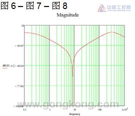
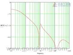
Description: This figure explains the system transfer function for handling large loads. The system reaches a peak at approximately 135 Hz, at which attempt to increase the gain will result in system instability and resonance. However, the use of a simple biquadratic filter provides a superior gain margin by increasing the lower frequency while truncating the higher frequencies. Therefore, with the digital filter system, the 10 Hz frequency range can be increased and the 135 Hz frequency range can be reduced.
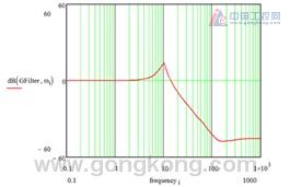
Description: This figure explains the shape of the transfer function when using a double quadratic filter.
Note: When the biquadratic filter is integrated into the transfer function of the resonant system, the high frequency is truncated and a flat response with higher gain is obtained. In this example, the resonance peak is reduced by 40 dB, which is equivalent to 100 gain. In this way, the gain can be scaled up to produce a high frequency response and a more stable system.
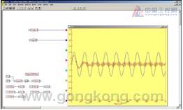
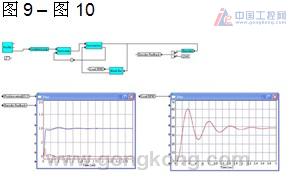
Description: The VisSim (Visual Solutions) model of a compatible mechanical system is used to analyze the operation of the controller. The figure on the right shows that the controller is vibrating when correcting the position loop. This is what happens when the gantry uses a belt drive at high inertia mismatch ratios. The amplitude of the load movement is significantly larger than the recognition range of the control system, and the echo causes vibration.
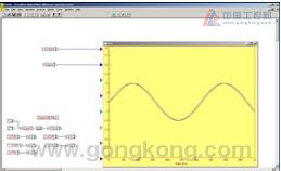
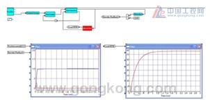
Note: When the inertia ratio of the load motor is reduced from 50:1 to 10:1, the stability increases and the clear position and velocity map shows no vibration. The acceleration time is reduced, the actual speed trajectory is closer to the command, and the correction time is reduced to the utmost.